
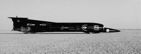
In previous In Depth articles, we've covered most aspects of the design of ThrustSSC from chassis and suspension, through to aerodynamics, communications, engines and systems, but there is one very important area not described until now - those round things that stop the bottom scraping on the floor and ensure that Thrust is actually a car and not a motor cycle or an aeroplane. Confused? Here's Glynne Bowsher to clarify things.
The Land Speed Record rules are quite simple but explicit with regard to wheels; if a vehicle is to be considered as a car, then it must be fitted with at least four of them, and controlled or steered by at least two of them. The clear implication of this is that three wheelers are not cars, hence the reason Craig Breedlove fell foul of the rules with his first Spirit of America. With only 3 wheels it ended claiming the record as an experimental motor cycle and sidecar! Before the SSC project could get underway, there were two fundamental questions which had to be positively answered before a detailed design could begin: was it possible to evolve a shape which would be stable over the extreme speed range being considered, and was it possible to design wheels which would not 'explode' under the high stresses anticipated at very high rotational speeds. Whilst Ron Ayers worked at answering the first question, I did likewise with the second; fortunately, we were both able to say "yes" at the end of our investigations, and the project blossomed into the complete vehicle that we have today. Wheel design inevitably drew on the experience of operating Thrust 2 on the same desert intended for ThrustSSC, but the duty level of the new wheels was to prove significantly different. The vehicle shape produced by Ron Ayers, and its ground clearance, dictated a wheel of 34 inches in diameter; at the anticipated design speed of 850mph, this meant a rotational speed of 8,400 rpm, and as a measure of the difficulty in design, a radial acceleration at the periphery of the wheel equal to 34,000 times the force of gravity. This large number contrasts with the Thrust 2 wheels, which peaked at 22,500g 14 years ago. A clear connection with the former project came with the decision to try to use the same L77 light alloy material for their manufacture.
And the problems in design did not stop there. The completed ThrustSSC would, at 10 tonnes, be more than twice the weight of Thrust 2, and this would manifest itself in the increased width of the wheels to transfer this weight to the desert. Again, the Thrust 2 experience had been invaluable in understanding the size of the wheel 'footprint' at the desert surface for efficient vehicle operation. The finalised basic dimensions were 34 inch diameter for all wheels, with the fronts having a 10 inch tread width and the rears having a 6 inch tread width; apart from the large diameter and very high speeds anticipated, most of the wheel mass is concentrated at the rim, the worst place for stress generation! Developing wheel shapes for minimum stress is greatly helped by the use of computers and software for 'finite element stress analysis'; using this technique, the wheel shape can be finalised with a high degree of confidence, before commitment to costly machining. The latest techniques were available, allowing a 'three dimensional' analysis, which even allowed the stresses inside the bolt holes to be analysed. Of necessity, the webs of all wheels were kept straight in order to minimise stress, but the front wheels, with their large rims, could not initially be stressed within the strength limitations of the L77 material at the vehicle's maximum speed. This problem was solved by the simple expedient of leaving out the hole in the centre of the wheel! All stresses fell sufficiently to give the 'green light' for the front wheel design. The loss of the central hole did not affect the wheel mounting, which was to be between two half shafts, though it did make life more difficult for the subsequent machining. Both rear wheels needed the central hole feature for bearings and stub axles, but with the smaller of the tread widths, it was possible to again design within the limitations of the proposed material.
The diagrams show the finalised wheel shapes. A requirement of all wheels is that they should give minimum rolling resistance as an aid to forward speed, yet have high lateral resistance in order to give good lateral stability and steering control. The circumferential grooves in the front wheels 'bite' the desert in order to give this to the non-steered front wheels, whilst the cicumferential keels of the rear wheels also 'bite' the desert and allow the development of lateral steering forces to give directional control. An indication of the wheel stresses generated at the vehicle's maximum speed for the front wheels is given by a colour illustration where the highest stresses are indicated by the colour red, and the lowest by blue, with the spectrum colours giving the stress bands in between. Designing the wheels of the jet car, with all the modern aids, is the easy part; the difficulty to overcome once the wheel design had been finalised was their manufacture, as this would inevitably be a costly venture. It was with some trepidation that Richard Noble and I went to see Dunlop at their Coventry plant to discuss wheels and also brakes. Having designed the latter as a follow on to my design of the wheel brakes of Thrust 2, I was keen to investigate the possibility of 'carbon' brake discs. The latter is another story, but Richard and I came out of the meeting with John Whelan of Dunlop not only deciding to manufacture the wheels for us, but the brakes as well; not only that, they also brought in their sister company within the BTR Group, HDA Forgings, who undertook the manufacture of the L77 billets from which the wheels would be machined. As if this was not enough, Dunlop/HDA also manufactured the wheels for the rubber (Lightning) tyres which allowed the jet car to operate on the runway at Farnborough. Dunlop clearly gave invaluable support to the project at a critical time, and we are indebted to them. With the wheels finish machined, the fronts were mated to the half-shafts manufactured to tight tolerances by the Nelson (Lancs) company of PDS Engineering, and bolted up to meet the requirements of SKF who supplied all of the wheel bearings. The front wheel assemblies were balanced at Schenk (Banbury) by Jim Watson and Steve Hart, again to tight tolerances in view of the high speeds to be attained; the rear wheels were similarly balanced, but on a specially made mandrel.
It is an accurate old saying that 'the proof of the pudding is in the eating', and having gone through all the stages of design and manufacture with the wheels, the confidence needed for their use on the jet cat could only be gained by practically spinning them at high speed, where predicted stresses would be 'for real'. Spin testing took place at the DRA spin test facility at Farnborough under the sponsorship of the DRA, and through the good offices of Mike Smith who undertook the tests. All wheels were tested, and each reached an equivalent vehicle speed of no less that 910mph and an overstress of more than 15% on our anticipated maximum speed. Not only that, each wheel spent 5 minutes stress soaking at the high speed before being brought to rest. Wheel inspection after each test showed no problems in the areas of highest anticipated stress, and all wheels have been cleared for running at 850mph.
The 1996 Jordan experience of operating the wheels produced a mixed response. Compared with the Black Rock desert of our previous experience, Al Jafr proved to be considerably harder; the front wheels only just depressed the surface normally, and with the rears riding on the original central ÔkeelŐ rather than the full width of the wheel. In complete contrast, there were parts of the desert which were very soft and here the wheels could plough the surface instead. Although the front wheels performed without problems on this variable surface, the rears were seen to develop a 'shimmy' as the speeds increased; an onboard video camera clearly showed this prior to its view being lost in the desert dust cloud. Wheel 'shimmy' can be the result of several factors, but with a project like this, there is no time for a proper development exercise. Accordingly, the problem has been discussed with several outside groups; the suspension geometry has now been changed, and apart from a few other changes, we now have new rear wheels with sport twin keels to give improved surface damping. It is here that the strength of our sponsors came to the fore; Dunlop had foreseen the possibility of a change in the wheel tread as the running experience developed, and had available two rear wheels fully machined with the exception of the tread. It was a simple matter to finish machining these wheels with the twin keeled tread, and these are now fitted to the jet car. The new Jordan experience will hopefully prove their worth.
This then is the wheel story, a story mirrored in many other parts of the jet car, the combination of a dedicated team, and above all, our dedicated sponsors, have allowed the problems to be solved and the vehicle to be built to Ron Ayers' mould breaking design.
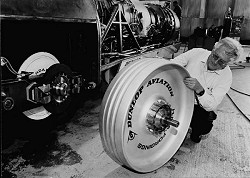
left: Glynne Bowsher, Chief Mechanical Engineer ThrustSSC, examining one of the solid aluminium wheels provided by Dunlop Aviation for use in the World Land Speed (LSR) attempt. Left side of photo shows one of the carbon brakes also provided by Dunlop Aviation. Photo ©Tony Dolphin Associates.
 |
 |
 |
||
| Sponsored by | This site best viewed with Microsoft Internet Explorer 3 | |||